
A stability chamber is a specialized environmental control instrument used to simulate real-world storage conditions and evaluate the quality, safety, and shelf life of pharmaceutical products over time. Regulatory agencies such as the US FDA, EMA, and WHO require stability studies in qualified chambers before granting marketing approval for new drug substances and drug products.
These chambers provide precisely controlled temperature and relative humidity (RH) conditions according to ICH stability guidelines. By exposing medicines to long-term, intermediate, and accelerated conditions, manufacturers can predict how products will behave in different climatic zones and throughout their shelf life.
How Does a Stability Chamber Work? (Working Principle)
A stability chamber maintains temperature using heating and cooling coils and controls humidity using humidification and dehumidification systems. A programmable logic controller (PLC) continuously receives signals from temperature and humidity sensors and adjusts heaters, refrigeration, and moisture systems to keep conditions within ICH tolerances (typically ±2–3°C and ±5% RH).

Detailed Explanation
1. Temperature Control
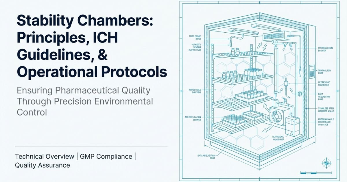
Inside the chamber, air temperature is controlled by a combination of:
- Refrigeration system (compressor, condenser, evaporator coil)
- Electric heaters mounted in the air circulation path
- Blowers/fans that ensure uniform air distribution
A primary temperature sensor (often a Pt100 RTD) measures the actual temperature (process value, PV). The PLC or PID controller compares this PV with the setpoint (SP) (e.g., 25°C, 30°C, or 40°C) and adjusts heater and refrigeration output to keep the temperature within ±2–3°C tolerance.
2. Humidity Control and Physics Behind It
Humidity in the chamber is measured as relative humidity (RH)—the ratio of actual water vapor in the air to the maximum it can hold at a given temperature.
- As temperature increases, the air’s capacity to hold water vapor (saturation vapor pressure) rises exponentially—described by the Clausius–Clapeyron equation.
- However, RH does not automatically increase with temperature. In fact, if no extra moisture is added, RH usually drops when temperature rises.
Therefore, stability chambers independently control humidity, rather than relying on temperature alone:
- Humidification systems:
- Steam generator
- Water spray nozzles
- Ultrasonic humidifiers
These add moisture into the airstream to increase RH.
- Dehumidification systems:
A capacitive humidity sensor (or equivalent) monitors the actual RH. The PLC compares this with the setpoint (e.g., 60%, 65%, or 75% RH) and proportionally adjusts humidification or dehumidification to maintain RH within ±5% of the setpoint.
3. Role of the PLC and PID Control
Most modern stability chambers are PLC-based with an HMI (Human–Machine Interface) touchscreen:
- The PLC collects signals from temperature and humidity sensors
- A PID (Proportional–Integral–Derivative) algorithm calculates how much heating, cooling, humidification, or dehumidification is needed
- The system continuously adjusts outputs to maintain stable conditions without overshoot or oscillation
This closed-loop control is essential for GMP compliance and for generating reliable, reproducible stability data.

ICH Stability Testing Conditions and Climatic Zones
The International Council for Harmonisation (ICH) provides harmonized guidelines (Q1A–Q1F) for stability testing of new drug substances and products. These guidelines define standard storage conditions based on climatic zones.
Common ICH Storage Conditions
| Study Type | Condition (Temp/RH) | Typical Use |
|---|---|---|
| Long-term (Zone II) | 25°C ± 2°C / 60% RH ± 5% | Temperate/mild climates (EU, US, Japan) |
| Long-term (Zone IVb) | 30°C ± 2°C / 75% RH ± 5% | Hot, very humid (e.g., India, SEA) |
| Intermediate | 30°C ± 2°C / 65% RH ± 5% | For specific formulations |
| Accelerated | 40°C ± 2°C / 75% RH ± 5% | Stress testing, shelf-life prediction |
ICH also categorizes climatic zones (I–IVb) and expects manufacturers to select stability conditions based on intended markets.
Key ICH Requirements:
- Temperature must remain within ±2–3°C of the setpoint
- RH must remain within ±5% of the setpoint
- Chambers must be mapped and qualified (IQ/OQ/PQ)
- Data logging, deviation handling, and calibration must comply with GMP and, where applicable, 21 CFR Part 11 for electronic records

Why Stability Chambers Are Critical for Global Markets
A product manufactured in a temperate region (e.g., US or EU) may not be stable in hot and humid Indian conditions. To ensure a product remains safe and effective across different markets:
- Stability samples are kept in chambers programmed to Indian climatic conditions (e.g., 30°C/75% RH) even if the chamber is physically in a US or EU laboratory.
- Accelerated conditions (40°C/75% RH) allow manufacturers to simulate long-term effects in a shorter time, supporting faster decision-making during development.
This strategy helps manufacturers:
- Predict shelf life
- Justify storage conditions on labels
- Support regulatory submissions globally
Validation of Stability Chambers: IQ, OQ, and PQ
Before a stability chamber can be used for regulatory studies, it must be fully qualified following GMP principles.
1. Installation Qualification (IQ)
Purpose: Verify that the chamber is installed correctly.
Includes:
- Documentation of model, serial number, capacity
- Utility requirements (power, water, drainage)
- Verification of physical installation (level, ventilation, clearance)
- Instrument lists and calibration certificates (traceable to recognized standards)
2. Operational Qualification (OQ)
Purpose: Confirm the chamber operates according to design across its operating ranges.
Typical OQ Activities:
- Empty-chamber temperature and humidity mapping at key setpoints
- Checking alarm functions (high/low temperature, high/low RH, door open)
- Verifying HMI/PLC controls, setpoint changes, and data logging
- Assessing stabilization time and recovery after door opening
3. Performance Qualification (PQ)
Purpose: Demonstrate that the chamber performs correctly under actual working conditions (with product load).
Typical PQ Activities:
- Mapping with real or representative containers at intended load (50–80% chamber volume)
- Multi-day data collection (e.g., 72 hours) to confirm uniformity under load
- Maintaining temperature and RH within defined acceptance criteria
- Documented evidence that conditions are suitable for routine stability studies
Requalification:
OQ and PQ are usually repeated annually or after major maintenance (sensor replacement, significant repairs, relocation).

Temperature and Humidity Mapping: Ensuring Uniform Conditions
What Is Mapping?
Temperature and humidity mapping is a structured study that verifies uniform conditions throughout the stability chamber. It ensures that every storage location inside the chamber meets ICH tolerance limits.
Sensor Placement Strategy
Number and placement depend on chamber size:
- Small chambers: typically 9 sensors (3 × 3 grid)
- Medium chambers: 12–18 sensors
- Large walk-in chambers: ≥27 sensors
Probes are placed at:
- Corners (top, middle, bottom)
- Center of chamber
- Near door, air supply, and return vents
Sensors should be kept several centimeters away from walls and floor to avoid “dead zones” and measure actual storage conditions.
Acceptance Criteria
- Max temperature spread (ΔT) across sensors typically ≤ ±1.0°C
- Max RH spread typically ≤ ±3% RH
- Chamber should recover to set conditions within 10–15 minutes after a brief door opening
All mapping data and analysis must be documented and approved by QA.

Calibration and Maintenance of Stability Chambers
Why Calibration Is Important
Sensor drift and equipment wear can compromise stability data. Even a small drift (e.g., ±0.5°C or ±3% RH) may:
- Cause false out-of-spec results
- Lead to incorrect shelf-life estimates
- Trigger regulatory findings during inspections
Typical Calibration Frequency
- Annually for chambers in routine use
- Semiannually for critical or high-use chambers
- After any major repair or sensor replacement
Calibration should be performed using traceable reference instruments (e.g., Pt100 Class A RTD, certified humidity standards) and include As Found / As Left documentation.
SOP for Stability Chamber Operation (PLC + HMI)
Objective:
To lay down a procedure for operation of a stability chamber with PLC control and touch screen HMI (e.g., LABO type) in a pharmaceutical Quality Control (QC) laboratory.
Scope:
Applicable to all stability chambers installed in the QC Department of [Company Name] used for ICH stability studies.
Responsibility:
- QC Officer/Executive – Routine operation, recording, and initial troubleshooting
- QC Manager – Review, compliance, deviation handling
- QA Head – Overall accountability and approval

1. Pre-Operation Checklist
Before starting the chamber, verify:
- Chamber is validated (IQ/OQ/PQ completed) and within requalification due date
- Latest calibration status is valid
- Chamber interior is clean and free from spills or residues
- Shelves are intact and arranged for uniform air flow
- Water reservoir (if used) is filled with appropriate-quality water (e.g., DI water)
- Door gasket is intact and closes properly
- Stability study protocol is available (required conditions and duration)
2. Power On and HMI Overview
- Switch ON the mains on the chamber control panel.
- The Main Screen displays:
- Set Point (SP) and Process Value (PV) for temperature and humidity
- AT indicator (Auto-Tuning) for temperature and humidity controls
- REFRIG. SYS status (which refrigeration system is running)
- HUMID. SYS status (which humidification system is active)
- CHAMBER status (OFF MODE / STABILIZATION / RUNNING MODE) with countdown timer
- TEMP. SENSOR and HUMID. SENSOR selections (MAIN or STANDBY sensors)
- Alarm status strip below sensor status:
- Red – alarm active
- Yellow – alarm acknowledged
- Confirm that no critical alarms are active before proceeding.
3. Setting Temperature on HMI
- From the Main Screen, press the MENU button.
- Select TEMP. CONT. (Temperature Control) from the Main Menu.
- On the Temperature Control page:
- Enter the required temperature setpoint (e.g., 25.0°C, 30.0°C, 40.0°C).
- Set high and low alarm limits (e.g., high alarm +2–3°C above SP, low alarm −2–3°C below SP).
- Review or start auto-tuning (AT) if necessary (button at top-right).
- After adjustments, press SAVE to store the settings.
4. Setting Humidity on HMI
- From the Main Screen, press MENU and then select HUMID. CONT.
- On the Humidity Control page:
- Enter the required RH setpoint (e.g., 60% RH, 65% RH, 75% RH).
- Set high and low humidity alarm limits (e.g., high alarm +5% RH, low alarm −5% RH).
- Start auto-tuning if allowed by your SOP and necessary.
- Press SAVE to confirm and store the humidity settings.
5. Starting the System
- Ensure chamber door is closed and properly latched.
- Press the START button on the HMI.
- The PLC sequence usually operates as follows:
- Main contactor energizes
- After a 2-minute delay, blower and refrigeration system start
- After an additional ~30 seconds, heater and humidification system start under PID control
- The chamber enters STABILIZATION mode until SP and PV for both temperature and humidity converge within defined tolerances.
6. Viewing Scanner Readings (Mapping Channels)
Your chamber may be equipped with an 8-channel scanner integrated with the PLC and HMI, typically configured as:
- TEMP 1–TEMP 4: Temperature probes at different locations
- HUMI 1–HUMI 4: Humidity probes at different locations
To view readings:
- From the Main Screen, press VIEW.
- The scanner page will show:
- TEMP 1–4 values with color coding:
- Normal background – within range
- Red – above upper limit
- Blue – below lower limit
- HUMI 1–4 values with similar color coding
- TEMP 1–4 values with color coding:
- Record readings as per your data recording schedule (e.g., once per day or per protocol).
7. Viewing Graphs and Trends
- Select GRAPH VIEW from the Main Menu.
- Press TRENDS and choose Temperature or Humidity.
- Observe trend lines to:
- Confirm stable behavior (no continuous drift)
- Check response after door opening or power interruption
- Support investigations in case of deviations
8. Generating and Printing Reports
- From the Main Menu, select SYSTEM → REPORT HEADER SETTING.
- Enter:
- Equipment Name
- Equipment ID
- Department Name
- Company Name
- Report Header/Title
- Press SAVE.
- To print historical data:
- Select OFFLINE PRINT from the Main Menu.
- Choose REPORT TYPE (e.g., daily, weekly, custom).
- Enter START PRINT DATE/TIME and END PRINT DATE/TIME (DD/MM/YY and HH:MM).
- Set the PRINT INTERVAL (e.g., 60 min).
- Press PRINT to generate a log on the connected printer or export data if supported.
9. Alarms, Deviations, and Troubleshooting
Common issues and actions:
| Issue | Possible Cause | Recommended Action |
|---|---|---|
| Temp above setpoint by >3°C | Refrigeration failure, overloaded chamber | Reduce load, check refrigeration, call engineering |
| Temp below setpoint by >3°C | Heater failure, setpoint misconfigured | Check heater and settings, call engineering |
| RH too high (>setpoint + 5% RH) | Excess humidification, door leakage | Inspect humidifier and door gasket, adjust RH |
| RH too low (<setpoint − 5% RH) | Dehumidifier overactive, water supply issue | Verify water level, adjust dehumidifier settings |
| Sensor readings unstable or erratic | Loose connections, failing sensor | Check/secure connectors, replace sensor if needed |
| Alarm active but chamber appears normal | Alarm limits incorrect or sensor drift | Verify with reference instrument, recalibrate |
Deviation Handling:
- Record deviations in Stability Chamber Deviation Log.
- Assess impact on ongoing studies (time and extent of out-of-spec conditions).
- Execute corrective and preventive actions (CAPA).
- Get QA review and approval before closing deviations.
10. Shutdown Procedure
- Stop the chamber through the HMI using the STOP or SHUTDOWN function.
- Allow the system to run its internal cool-down cycle if configured.
- Wait until temperature is close to ambient before opening the door.
- Remove samples as per study termination procedure.
- Turn OFF the mains when chamber is not required, as per your energy and equipment policy.
Summary
The working principle of a stability chamber is based on precisely controlling temperature and relative humidity using heaters, refrigeration, and humidification/dehumidification systems under PLC/PID control. The chamber’s performance is verified and maintained through:
- Strict adherence to ICH stability conditions
- Qualification (IQ/OQ/PQ) and regular mapping
- Calibration with traceable standards
- Robust SOPs governing operation, monitoring, alarms, and deviations
While basic principles are similar across industries, pharmaceutical stability chambers must comply with stringent GMP, ICH, and regulatory guidelines, making detailed SOPs and documentation critical for successful inspections and regulatory submissions.
Frequently Asked Questions (FAQ)
-
How does a stability chamber maintain both temperature and humidity?
A stability chamber uses independent but coordinated systems. Heating and cooling elements regulate temperature, while humidification (steam or water spray) and dehumidification (desiccant or refrigeration) regulate humidity. A PLC continuously reads temperature and humidity sensors and automatically adjusts each system to maintain the setpoints within ICH tolerances.
-
What are the standard ICH stability conditions?
Typical ICH conditions include 25°C/60% RH for long-term storage in temperate regions and 30°C/75% RH for long-term storage in hot, humid zones such as India. Accelerated stability studies commonly use 40°C/75% RH. These conditions help predict product shelf life across different climatic zones.
-
Why is mapping of stability chambers required?
Temperature and humidity mapping verify that the entire usable volume of the chamber meets defined uniformity criteria (usually ≤±1.0°C and ≤±3% RH). This ensures that every storage location is suitable for samples. Regulatory guidelines and good engineering practices require mapping during qualification and periodic requalification.
-
How often should a stability chamber be calibrated?
In most pharmaceutical facilities, stability chambers are calibrated at least annually. Critical chambers or those with drift history may be calibrated semiannually. Calibration should be done using traceable reference instruments and documented with As Found/As Left readings. Any significant drift should trigger investigation and possible impact assessment on stability studies.
-
What is the difference between IQ, OQ, and PQ in stability chambers?
IQ (Installation Qualification): Confirms that the chamber and its components are installed correctly and according to specifications.
OQ (Operational Qualification): Demonstrates that the chamber operates correctly across its intended operating ranges (usually includes initial mapping).
PQ (Performance Qualification): Shows that the chamber maintains conditions within specifications under normal working (loaded) conditions. All three stages are required for GMP-compliant use.
References
- US Food and Drug Administration (FDA). 21 CFR Part 211 – Current Good Manufacturing Practice for Finished Pharmaceuticals.
- ICH Q1A(R2). Stability Testing of New Drug Substances and Products.
- EMA/ICH Q1 Guideline on Stability Testing of Drug Substances and Drug Products.
- Withnell Sensors. Stability Chambers That Meet ICH Guidelines for Pharmaceutical Stability Testing (2023).
- Vici Health Sciences. Stability Chamber Validation & Storage Conditions Explained (2025).
- Lumen Learning. Humidity, Evaporation, and Boiling – Physics.
Wikipedia. Humidity. - Eurotherm. PLC or PID Controller: What’s the Difference and How Do You Decide? Stability Hub / Various Industry Sources. Stability Chamber Validation, Calibration & Mapping Guidance.
- Enviro-Technologies. Everything About Stability Chambers – Functions & Uses (2024).
- FDA Group. Basic Guide to IQ/OQ/PQ in FDA-Regulated Industries (2024).
- SimplerQMS / Industry Guidance. Pharmaceutical Calibration: Definition, Importance & Practices (2026).


